The second thing I noticed was that my RPM readout was all over the place (800-2200 @1550RPM actual).
After alot of troubleshooting, it turned out to be my cheap "DVE" 12V power supply running the Arduino was entirely the problem. I discovered this after I tried a battery in place of the Arduino power supply.. and then tried another power supply.

Luckily I found it pretty quick but for people having trouble with their DIY tach sensor circuits and readings, keep my experience here in mind.
Quick overview, I'm using TouchDRO with the Arduino controller based hardware and Rysiu M's firmware. I wired in a tach sensor using this IR tx/rx hardware. It's got two IR sensors, I just used one. The little "motherboard" cleans up the IR sensor signal into a digital pulse train which gets fed into Arduino pin D7. More details are here.
Initially, looking at the signal on pin D7 (the tach input pin to Arduino) I thought it was clean and stable. I triggered on it nicely and noticed that some pulses seemed to shift width just a hair, like 1 pixel on my scope's LCD screen. I watched the Hz and period measurements on screen and figured that they were moving less than what I was seeing on the RPM readout, even accounting for scaling from Revs Per/Sec to Revs Per/Min.
 |
| Pin D7 pulses with DVE power supply, looked good to me initially. |
I poked around with the scope looking at signals and grounding things, none of it producing any real result. The next day, at some point I zoomed in on one of the D7 pulses.... bouncing!
 |
| DVE PS zoom into front edge of tach sensor pulse, bouncing(intermittently, not always). Also present on trailing edge sometimes. |
Below are some pictures that show what the bad power supply was producing, with the VFD on there was over 1 V of noise riding on the 12V DC.
 |
| DVE Power Supply, no load, VFD stop (AC Coupled .5V/div), |
 |
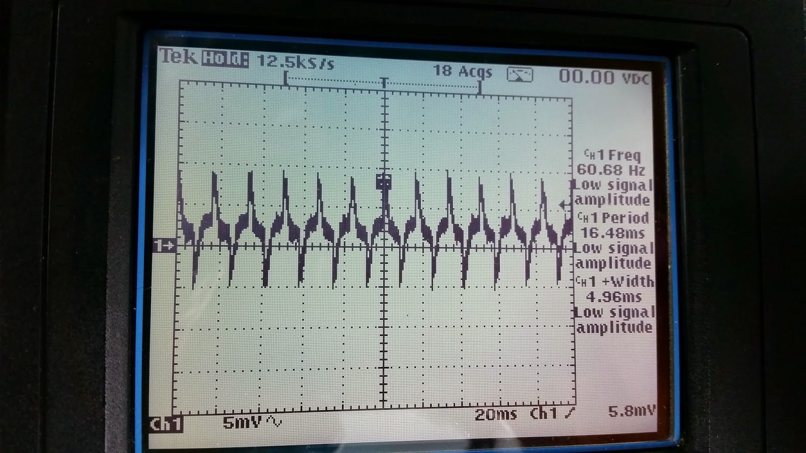
| DVE Power Supply powering Arduino, VFD Run. (AC Coupled .5V/div), |
Below are pictures of the new Netgear power supply I dug up. It's worst case was 15mV at no load.... when powering the Arduino it was actually almost within 5mV.
 |
| Netgear Power Supply, no load, VFD stop (AC Coupled .005V/div) |
 |
| Netgear Power Supply, powering Arduino, VFD run (AC Coupled .005V/div)This is better than picture above showing no load/no VFD run. |
 |
| Netgear PS, D7 signal, VFD run. |
 |
| Netgear PS, D7 signal pulse leading edge, VFD run |
 |
| Netgear PS, D7 signal pulse trailing edge, VFD run |
Anyway, I think i'm going to switch to USB power for the Arduino. I'd like to have a USB cable coming out of the box it's all mounted in anyway.
No comments:
Post a Comment